All posts by Said Yahya

Step Down Transformer: How Does it Work? (Formula & Working Principle)

What Is A Step Down Transformer

What is a Step Down Transformer?

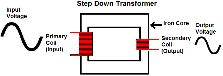
A transformer is a type of static electrical equipment that transforms electrical energy (from primary side windings) to magnetic energy (in transformer magnetic core) and again to the electrical energy (on the secondary transformer side). A step-down transformer has a wide variety of applications in electrical systems and transmission lines.

A step-down transformer is a type of transformer that converts the high voltage (HV) and low current from the primary side of the transformer to the low voltage (LV) and high current value on the secondary side of the transformer. The reverse of this is known as a step up transformer.

step down transformer

When it comes to the operation voltage, the step-up transformer application can be roughly divided into two groups: LV (voltages up to 1 kV) and HV application (voltages above 1 kV).

Just as transformers can step down the voltage – going from a higher primary side voltage to a lower secondary side voltage – they can also step up the voltage, going from a lower primary side voltage to a higher secondary side voltage. These are known as step-up transformers.

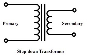
The transformer turns ratio (n) for a step down transformer is approximately proportional to the voltage ratio:

\begin{align*} n = \frac{V_{P}}{V_{S}} = \frac{N_{P}}{N_{S}} \end{align*}


Where VP,S are voltages, and NP,S are the turns numbers on the primary (LV) and secondary (HV) sides respectively. The primary side of a step-down transformer (HV side) has a larger number of turns than the secondary side (LV side).

That means energy flows from the HV to the LV side. The voltage is stepped down from the primary voltage (input voltage) to the secondary voltage (output voltage).

This equation can be rearranged for the formula for the output voltage (i.e. secondary voltage). This is sometimes referred to as the step down transformer formula:

\begin{align*} V_{S} = \frac{N_{S} * V_{P}}{N_{P}} \end{align*}


A transformer calculator can help you easily calculate the transformer turns ratio and whether the device is a step down or step up transformer.

The first LV application refers to the transformers in electronic devices. Supplying the electronic circuits requires a low voltage value (e.g. 5V, even lower values nowadays).

A step-down transformer is used to provide this low voltage value which is suitable for electronics supplying. It transforms home voltage (230/120 V) from primary to a low voltage on the secondary side which is used for electronic supplying.

If electronic devices are designed to have higher nominal power, transformers with high operating frequency are used (kHz-s). The transformers with higher nominal power value and 50/60 Hz nominal frequency would be too large and heavy. Also, the daily used battery chargers use the step-down transformer in its design.

Step Down Transformer Applications

The step-down transformers have a very important function in a power system. They lower the voltage level and adapt it to energy consumers. It is performed in several steps described below:

  • A long distance energy transmission system should have a voltage level as high as possible. With high voltage and low current, the transmission power losswill be significantly decreased. A power grid is designed that has to be connected with the transmission system with the different voltage levels. Step-down transformers are used in the interconnection of transmission systems with different voltage levels. They decrease voltage level from high to lower value (e.g. 765/220 kV, 410/220 kV, 220/ 110 kV). These transformers are huge and have very high nominal power (even 1000 MVA). In this case, when the transformer turns ratio is not high the autotransformers are usually installed.
  • The next voltage level transformation step is adapting the transmission voltage to the distribution level. The characteristic voltage ratios, in this case, are 220/20 kV, 110/20 kV (also the LV secondary voltages 35 kV and 10 kV can be found). The nominal power of those transformers is up to 60 MVA (usually 20 MVA). The on-load tap changer is almost always installed in these transformers. Voltage regulation is the main function of tap changer. In the USA the tap changer is based on the LV side, and in the rest of the world mostly on the HV transformer side.
  • The final voltage transformation step is adapting the voltage to the home voltage levelThese transformers are known as small distribution transformers with nominal power up to 5 MVA (mostly below 1 MVA) and with nominal voltage values 35, 20, 10 kV on HV side and 400/200 V on LV side. It is noticeable that those transformers have ahigh turns ratio. They usually have de-energized tap changer with 5 tap position (+/- 2 tap position) and do not have on-load tap changer.

What is Atom and its structure ?

 Atom

An atom is the smallest unit of ordinary matter that forms a chemical element. Every solid, liquid, gas, and plasma is composed of neutral or ionized atoms. Atoms are extremely small, typically around 100 picometers across. They are so small that accurately predicting their behavior using classical physics—as if they were tennis balls, for example—is not possible due to quantum effects.AtomAn illustration of the helium atom, depicting the nucleus (pink) and the electron cloud distribution (black). The nucleus (upper right) in helium-4 is in reality spherically symmetric and closely resembles the electron cloud, although for more complicated nuclei this is not always the case. The black bar is one angstrom (10−10 m or 100 pm).ClassificationSmallest recognized division of a chemical elementPropertiesMass range1.67×10−27 to 4.52×10⁻²⁵ kgElectric chargezero (neutral), or ion chargeDiameter range62 pm (He) to 520 pm (Cs) (data page)ComponentsElectrons and a compact nucleus of protons and neutrons

Every atom is composed of a nucleus and one or more electrons bound to the nucleus. The nucleus is made of one or more protons and a number of neutrons. Only the most common variety of hydrogen has no neutrons. More than 99.94% of an atom’s mass is in the nucleus. The protons have a positive electric charge, the electrons have a negative electric charge, and the neutrons have no electric charge. If the number of protons and electrons are equal, then the atom is electrically neutral. If an atom has more or fewer electrons than protons, then it has an overall negative or positive charge, respectively – such atoms are called ions.

The electrons of an atom are attracted to the protons in an atomic nucleus by the electromagnetic force. The protons and neutrons in the nucleus are attracted to each other by the nuclear force. This force is usually stronger than the electromagnetic force that repels the positively charged protons from one another. Under certain circumstances, the repelling electromagnetic force becomes stronger than the nuclear force. In this case, the nucleus splits and leaves behind different elements. This is a form of nuclear decay.

The number of protons in the nucleus is the atomic number and it defines to which chemical element the atom belongs. For example, any atom that contains 29 protons is copper. The number of neutrons defines the isotope of the element. Atoms can attach to one or more other atoms by chemical bonds to form chemical compounds such as molecules or crystals. The ability of atoms to associate and dissociate is responsible for most of the physical changes observed in nature. Chemistry is the discipline that studies these changes.

What is deference between weight and mass ?

Mass And Weight

What is Mass?

It is one of the fundamental quantities in Physics and the most basic property of matter. We can define mass as the measure of the amount of matter in a body. The SI unit of mass is Kilogram (kg).

Note: The mass of a body does not change at any time. Only for certain extreme cases when a huge amount of energy is given or taken from a body. For example: in a nuclear reaction, tiny amount of matter is converted into a huge amount of energy, this reduces the mass of the substance.More On MassMeasurement of MassCenter of Mass

What is Weight?

It is the measure of the force of gravity acting on a body.

The formula for weight is given by:

w = mg

As weight is a force its SI unit is also the same as that of force, SI unit of weight is Newton (N). Looking at the expression of weight we see that it depends on mass and the acceleration due to gravity, the mass may not change but the acceleration due to gravity does change from place to place. To understand this concept let’s take this example,

Shape of the earth is not completely spherical, but an oblate spheroid, therefore a person standing at the equator is far away from the center of the earth than a person standing at the north pole, as acceleration due to gravity is proportional to the inverse of the square of the distance between two objects, a person standing at the north pole would experience more weight as he is closer to the center of the earth than a person standing at the equator.

How is Weight Measured?

Following is the formula of a body which has a mass m and weight of magnitude w:w = mg

So it can be said that the weight of an object is directly proportional to its mass.

Mass And Weight

 What is the Difference between Mass and Weight?

Mass

Weight

Mass can never be zero.Weight can be zero. As in space if no gravity acts upon an object, its weight becomes zero.Mass is a scalar quantity. It has magnitude.Weight is a vector quantity. It has magnitude and is directed toward the center of the Earth or other gravity well.Mass is commonly measured in kilograms and grams.Weight is commonly measured in Newtons.Mass doesn’t change according to location.Weight varies according to location.The mass may be measured using an ordinary balance.Weight is measured using a spring balance.

Mass And Weight

What is Weightlessness?

Have you ever been in an elevator? Noticed how you feel like your weight is been reduced while the elevator goes down? That is because the weight you feel is the perceived weight or “effective weight”, this is the equal and opposite force the floor exerts on you due to your weight. Now if we remove the floor and let you fall freely, there is nothing to exert a force on you and hence you will feel weightless even though there is acceleration due to gravity and mass. This is because the effective weight is equal to zero. Now, let’s come back to our elevator when the elevator is going down it is actually moving in the direction of the gravity, hence reducing net acceleration due to gravity, thereby reducing your weight.
The same happens with astronauts in the international space station, as the space stations are orbiting the earth it is actually falling towards the earth indefinitely and everything in it is falling including the astronauts so the astronauts experience weightlessness and can float freely around. In all these scenarios the most important thing we have to notice is that weight can increase or decrease depending on the acceleration due to gravity but the mass remains unchanged.

Relation Between Weight and Mass

Consider a body having large mass and large weight. Example of this situation is a large object which is hard to throw because the weight of this object is large.

Therefore, the relation between weight and mass can be derived with the help of Newton’s second law which explains that the free falling object has an acceleration “g” as the magnitude.

If an object with a mass of 1kg falls with an acceleration of 9.8 m.s-2, then the magnitude of the force is given as :
F = ma
= (1kg)(9.8m.s-2)
= (9.8 kg.m.s-2)
= 9.8N

Therefore, it can be concluded that the relation between weight and mass of an object with 1kg mass will have a weight of 9.8N.

What is a Capacitor? Definition, Uses & Formulas in Series and Parallel?

What is a Capacitor? Definition, Uses & Formulas in Series and Parallel

1018_capacitor_basics_main

Capacitance is the ability of an object to store an electrical charge. While these devices’ physical constructions vary, capacitors involve a pair of conductive plates separated by a dielectric material. This material allows each plate to hold an equal and opposite charge. This stored charge can then release as needed into an electrical circuit. A capacitor may be an electrical component, but many objects, such as the human body, exhibit this ability to hold and release a charge. As we’ll note, this ability can be advantageous.

Capacitance Equation

The basic formula governing capacitors is:

charge = capacitance x voltage

or

Q = C x V

We measure capacitance in farads, which is the capacitance that stores one coulomb (defined as the amount of charge transported by one ampere in one second) of charge per one volt. While a convenient way to define the term, everyday capacitors aren’t big enough to store a single farad, so we often display ratings in terms of microfarads (μF, or millionths of a farad), or even picofarads (pF, or trillionths of a farad).

From this definition, you might assume that a capacitor is a type of rechargeable battery, storing charge to use later. However, a capacitor’s characteristically low charge capacity compared to conventional battery cells generally makes them ill-suited to prolonged use as a power source. The other characteristic that makes them disadvantageous for prolonged power delivery is that a capacitor’s voltage is directly proportional to the amount of stored charge, evidenced by rearranging the terms in the above equation to:

V = Q/C

Conventional batteries hold a somewhat steady charge until depleted, making them more appropriate in many situations.

Power Smoothing and Time Constant

Prolonged usage aside, capacitors do a very good job of evening out momentary drops in power. The time constant tau indicates this capability. Tau equals resistance times capacitance:

τ = RC

Tau indicates the amount of time in seconds that it takes a voltage to decay exponentially to 37 percent of its original value. At five times this number, the capacitor is considered fully discharged. If a capacitor attaches across a voltage source that varies (or momentarily cuts off) over time, a capacitor can help even out the load with a charge that drops to 37 percent in one time constant. The inverse is true for charging; after one time constant, a capacitor is 63 percent charged, while after five time constants, a capacitor is considered fully charged.

1018_capacitor_basics_inset_1

Image: PartSim Drawing by Jeremy S. Cook

For example, if you had a circuit as defined in Figure 1 above, the time constant of the RC circuit is:

1000 ohms x 47 x 10-6 farads

This time constant works out to .047 seconds. When we disconnect the 5V source seen here, it takes .047 seconds to drop to 1.85V, and five times this, or .235 seconds, to discharge. If the capacitor charged up to 5V, that process would also take .235 seconds. You can use a larger capacitor to increase these numbers depending on the situation or load in question.

What Else is a Capacitor Used For?

Making an intermittent voltage supply closer to a desired constant voltage is a capacitor’s most fundamental purpose. Here are several more ways to use a capacitor:

  1. AC to DC conversion. The DC output tends to vary sinusoidally in this important “smoothing” application.
  2. Coupling. A standard capacitor allows AC to pass and stops DC.
  3. Decoupling. Capacitors can also eliminate any AC that may be present in a DC circuit.
  4. RF signals and older radios. You can adjust variable “tuning” capacitors to change the station — you can even build your own radio as an educational tool this tutorial
  5. Timers. Use the time it takes a capacitor to charge to a certain level to trip other parts of the circuit. As with RF tuning, integrated circuits and microcontrollers have largely replaced capacitive timing functions.
  6. Touchscreens. Though exotic when compared to other circuits described here, a capacitive touchscreen is an extremely common way to use a capacitor. These devices sense the change in capacitance at a point on a display device and translate it into coordinates on an X-Y plane.
  7. Microscopic capacitors. These devices serve as data storage units in Flash memory. Considering the innumerable number of bits in Flash memory, microscopic capacitors contain the largest number of capacitors in use today.

Capacitors in Series and Parallel

Capacitors, like resistors, can combine in parallel or series within a circuit. However, the net effect is quite different between the two. When done in parallel, combining capacitors mimics adding each capacitor’s conductor and dielectric surface area. In parallel, the total capacitance is the sum of each capacitor’s value.

Capacitance in series reduces the total amount of capacitance, such that the total capacitance of these components in total will be less than the value of the smallest capacitor value. The equation is given by:

1/CT = 1/C1 + 1/C2 + 1/Cn

Series usage is less common than parallel configurations, but dividing the voltage applied to each component has some limited uses.

Leyden Jar:  History of Capacitors and Their Structure

1018_capacitor_basics_inset_2

The first capacitor was called the Leyden Jar. These early charge storage devices were full of water and served as conductors, but they eventually evolved into a glass bottle with metallic foil coating the inside and the outside of the bottle. The foil acts as conductors separated by glass, which acts as a dielectric material. The two segments store charges between them until connected.

Today’s capacitors come in many shapes in sizes, but at their core, they have two electrically conducting “plates” separated by a dielectric insulating material. The governing equation for capacitor design is:

C = εA/d,

In this equation, C is capacitance; ε is permittivity, a term for how well dielectric material stores an electric field; A is the parallel plate area; and d is the distance between the two conductive plates.

1018_capacitor_basics_inset_3

Image: By Eric Schrader via Wikimedia Commons

You can split capacitor construction into two categories, non-polarized and polarized.  

  • Non-polarized capacitors are most like the theoretical capacitor we described earlier. They contain a pair of conducting plates separated by a dielectric and they can connect to a source voltage in either electrical orientation. Ceramic capacitors contain several plates stacked on top of one another to increase the surface area, while a ceramic material forms the dielectric between the positive and negative poles. Film capacitors wrap these plates against each other, and the dielectric film is usually plastic.
  • Polarized capacitors are electrolytic. An electrolytic capacitor’s anode can form an insulating oxide layer that acts as a dielectric. Because this oxide layer is extremely thin, the denominator in the C = εA/d equation is very small, thus enhancing these components’ capacitance. Additionally, the surface area component can be quite high per component volume because the anode material (generally aluminum, tantalum, or niobium) can be rough or porous.

You could classify a supercapacitor as a type of electrolytic capacitor, though a supercapacitor’s charge storage method involves the arrangement of ions in an electrolytic solution between two electrodes to form a double layer of charged ions. This arrangement gives an extremely high charge compared to traditional electrolytic and non-polarized capacitors but also results in a slower charge and discharge rate as well as a typically lower breakdown voltage. Because of this slow speed, a supercapacitor isn’t appropriate for filtering applications. One might even argue supercapacitors are in a class all unto themselves, and supercapacitor technology merits its own research.

Capacitor Specifications

A capacitor’s most basic rating is its capacitance, as we’ve mentioned. Capacitance specifies a capacitor’s charge-holding capability per volt. Beyond that, you can specify a capacitor by the following:

  • Working Voltage: The voltage above which a capacitor may start to short and no longer hold a charge
  • Tolerance: How close to the capacitor’s charge rating the actual component will be
  • Polarity: Which lead is meant to connect to a positive lead, and which goes to a negative in the case of polarized capacitors
  • Leakage Current: How much current will seep through a dielectric, gradually discharging a capacitor over time
  • Equivalent Series Resistance (ESR): The capacitor’s impedance at high frequencies
  • Working Temperature: Temperature range at which a capacitor is expected to perform nominally
  • Temperature Coefficient: Change in a capacitor’s charge holding performance over a specified temperature range
  • Volumetric Efficiency: While not always considered or explicitly specified, this factor indicates how much capacitance the component exhibits for a certain volume.

A Fundamental Passive Component

Along with resistors and inductors, capacitors act as one of the fundamental passive components that form the circuits we use every day. While the concept of two opposite charges on plates is simple, their application, and the wide variety of manufacturing techniques and form-factors available, is not. The good news is that whatever your charge storage issue, there’s probably a capacitor out there that will fit your application perfectly. 

What is the types of Electrical Relays ?

Types of Electrical Relays

my2n dc24 by omz

There are two basic classifications of relays:

  1. Electromechanical Relays
  2. Solid State Relays

One main difference between them is electromechanical relays have moving parts, whereas solid state relays have no moving parts. In addition to them there are different types of protective relays available in the industry.

Electromechanical Relays

Electromechanical relays are switches that typically are used to control high power electrical devices.

Electromechanical relays are used in many of today’s electrical machines when it is vital to control a circuit, either with a low power signal or when multiple circuits must be controlled by one single signal. 

Advantages of Electromechanical relays include lower cost, no heat sink is required, multiple poles are available, and they can switch AC or DC with equal ease.

Some of the electromechanical relays are

  1. general purpose relays,
  2. power relay,
  3. contactor and
  4. time delay relay.

Each of them are briefly explained here.

General Purpose Relay

The general-purpose relay is rated by the amount of current its switch contacts can handle. Most versions of the general-purpose relay have one to eight poles and can be single or double throw.  General Purpose Relay

General Purpose Relays are cost-effective 5-15 Amp switching devices used in a wide variety of applications. These are found in computers, copy machines, and other consumers electronic equipment and appliances. 

Typical Applications: Lighting controls, time delay controls, industrial machine controls, energy management systems, control panels, forklifts, HVAC.

Power Relay

%2524 35

The power relay is capable of handling larger power loads 10-50 amperes or more. They are usually single-pole or double-pole units.Power Relay

Power relays also contain an armature, a spring and one or several contacts. If the power relay is designed to normally be open, when power is applied, the electromagnet attracts the armature, which is then pulled in the coil’s direction until it reaches a contact, therefore closing the circuit.

If the relay is designed to be normally closed, the electromagnetic coil pulls the armature away from the contact, therefore opening the circuit.Power relays are used for many different applications, including:

  • Automotive electronics
  • Audio amplification
  • Telephone systems
  • Home appliances
  • Vending machines

Power relays are used for switching a wide variety of currents for applications including everything from lighting control to industrial sensors.

Contactor

A special type of high power relay, it’s used mainly to control high voltages and currents in industrial electrical applications. Because of these high power requirements, contactors always have double-make contacts.

Time-Delay Relay
solid%2Bstate%2Brelay%2Bthree%2Bphase
contactor%2Brelays

Contactor

These relays are switchgear devices for control and auxiliary circuits and are used to control, provide signals and interlock switching devices and switchgear panels.

A contactor is a large relay, usually used to switch current to an electric motor or other high-power loads. Large electric motors can be protected from overcurrent damage through the use of overload heaters and overload contacts.

If the series-connected heaters get too hot from excessive current, the normally-closed overload contact will open, de-energizing the contactor sending power to the motor.

Time-Delay Relay

The contacts might not open or close until some time interval after the coil has been energized. This is called delay-on-operate.

Delay-on-release means that the contacts will remain in their actuated position until some interval after the power has been removed from the coil.Time-Delay Relay

A third delay is called interval timing. Contacts revert to their alternate position at a specific interval of time after the coil has been energized.

The timing of these actions may be a fixed parameter of the relay, or adjusted by a knob on the relay itself, or remotely adjusted through an external circuit.

Solid State Relays

A solid-state relay (SSR) is an electronic switching device that switches on or off when a small external voltage is applied across its control terminals. 

SSRs consist of a sensor which responds to an appropriate input (control signal), a solid-state electronic switching device which switches power to the load circuitry, and a coupling mechanism to enable the control signal to activate this switch without mechanical parts. 

The relay may be designed to switch either AC or DC to the load. It serves the same function as an electromechanical relay, but has no moving parts. The figure below shows a three phase solid state relay.Solid State Relay

How Solid State Relay Works?

These active semiconductor devices use light instead of magnetism to actuate a switch. The light comes from an LED, or light emitting diode. When control power is applied to the device’s output, the light is turned on and shines across an open space.

On the load side of this space, a part of the device senses the presence of the light, and triggers a solid state switch that either opens or closes the circuit under control.Often, solid state relays are used where the circuit under control must be protected from the introduction of electrical noises.

  • Advantages of Solid State Relays include low EMI/RFI, long life, no moving parts, no contact bounce, and fast response. 
  • The drawback to using a solid state relay is that it can only accomplish single pole switching.

What is molecule ?


Molecule 

 A molecule is the smallest particle in a chemical element or compound that has the chemical properties of that element or compound. Molecules are made up of atoms that are held together by chemical bonds. These bonds form as a result of the sharing or exchange of electrons among atoms. The atoms of certain elements readily bond with other atoms to form molecules. Examples of such elements are oxygen and chlorine. The atoms of some elements do not easily bond with other atoms. Examples are neon and argon.

Molecules can vary greatly in size and complexity. The element helium is a one-atom molecule. Some molecules consist of two atoms of the same element. For example, O2 is the oxygen molecule most commonly found in the earth’s atmosphere; it has two atoms of oxygen. However, under certain circumstances, oxygen atoms bond into triplets (O3), forming a molecule known as ozone. Other familiar molecules include water, consisting of two hydrogen atoms and one oxygen atom (H2O), carbon dioxide, consisting of one carbon atom bonded to two oxygen atoms (CO2), and sulfuric acid, consisting of two hydrogen atoms, one sulfur atom, and four oxygen atoms (H2 SO4).

Some molecules, notably certain proteins, contain hundreds or even thousands of atoms that join together in chains that can attain considerable lengths. Liquids containing such molecules sometimes behave strangely. For example, a liquid may continue to flow out of a flask from which some of it has been poured, even after the flask is returned to an upright position.

Molecules are always in motion. In solids and liquids, they are packed tightly together. In a solid, the motion of the molecules can be likened to rapid vibration. In a liquid, the molecules can move freely among each other, in a sort of slithering fashion. In a gas, the density of molecules is generally less than in a liquid or solid of the same chemical compound, and they move even more freely than in a liquid. For a specific compound in a given state (solid, liquid, or gas), the speed of molecular motion increases as the absolute temperature increases.

What is Substance in Chemistry ?

Definition of Substance

A substance is matter which has a specific composition and specific properties.

Every pure element is a substance. Every pure compound is a substance.

Examples of substances: Iron is an element and hence is also a substance. Methane is a compound and hence is also a substance.

Examples of non-substances: Salt water is not a substance. It is a mixture of two substances – sodium chloride and water. Its composition and therefore its properties are not fixed. Gasoline is not a substance. It is a mixture of hydrocarbons and, depending on the composition of the gasoline mixture, gasoline’s properties can vary.

Power Supply: Definition, Functions & Components ?

Power Supply: Definition, Functions & Components

Definition: A power supply is an electronic circuit designed to provide various ac and dc voltages for equipment operation.

Proper operation of electronic equipment requires a number of source voltages. Low dc voltages are needed to operate ICs and transistors. High voltages are needed to operate CRTs and other devices. Batteries can provide all of these voltages.

However, electricity for electrical and electronic devices are commonly supplied by the local power company. This power comes out of an outlet at 115-volt ac, with a frequency of 60 Hertz. Different voltages are needed to operate some equipment.

Power Supply Functions

The complete power supply circuit can perform these functions:

  1. Step voltages up or step voltages down, by transformer action, to the required ac line voltage.
  2. Provide some method of voltage division to meet equipment needs.
  3. Change ac voltage to pulsating dc voltage by either half-wave or full-wave rectification.
  4. Filter pulsating dc voltage to a pure dc steady voltage for equipment use.
  5. Regulate power supply output in proportion to the applied load.

Power Supply Components

A block diagram illustrating these functions is shown in Figure 1. Note that certain functions are not found in every power supply. See Figure 2 for a typical commercial power supply components.

Block diagram for power supply components

Figure 1. Block diagram for power supply components. Input is 117 volts ac. Processes used in a typical power supply are shown below the blocks. The output of the power supply can be dc or ac. The output of this supply is five volts dc.

Regulated dc power supply

Figure 2. Regulated dc power supply. (Knight Electronics)

Power Transformers Diodes

The first device in a power supply is the transformer. Its purpose is to step up or step down alternating source voltage to values needed for radio, TV, computer, or other electronic circuit use.

Most transformers do not have any electrical connection between the secondary and primary windings. See Figure 3. This means that the transformer isolates the circuit connected to the primary from the circuit connected in the secondary.

Isolation in a transformer.

Figure 3. Isolation in a transformer.

Using an isolation transformer is a safety feature because it helps prevent shocks in the secondary. Our body or hands must be joined across both leads of the secondary connections in order to receive a shock.

The safety condition described above does not hold true in the primary with commercial ac provided by the power company. One connection is hot, which means that the connection is electrically energized. The other is grounded, or neutral. Standing on the ground while touching the hot connection will result in a shock. Touching the ground connection alone will not result in a shock.

Many power supplies use a center tap secondary transformer winding. The tapped voltages, Figure 4, are 180 degrees out of phase with respect to the center tap.

A variety of transformers can be found in nearly all electronic devices. You should understand the basic theory and purpose of the transformer. Review Chapter 12 if necessary.

A Lesson in Safety

Transformers produce high voltages that can be very dangerous. Proper respect and extreme caution must be used at all times when working with, or measuring, high voltages.

A center tap transformer.

Figure 4. A center tap transformer.

Half-Wave and Full-Wave Rectification

After a voltage has gone through a power supply’s transformer, the next step is rectification.

When changing an ac signal to dc, there are two types of rectification: half-wave rectification and full-wave rectification.

With the half-wave rectifier, only half of the input signal passes on through the rectifier. With the full-wave rectifier, the entire input wave is passed through.

Half-Wave Rectification

In Figure 5, the output of a transformer is connected to a diode and a load resistor that are in series. The input voltage to the transformer appears as a sine wave.

The polarity of the wave reverses at the frequency of the applied voltage. The output voltage of the transformer secondary also appears as a sine wave. The magnitude of the wave depends on the turns ratio of the transformer. The output is 180 degrees out of phase with the primary.

The top of the transformer (point A) is joined to the diode anode. Note that the B side of the transformer is connected to ground.

During the first half cycle, point A is positive. The diode conducts, producing a voltage drop across resistor R equal to IR. During the second half cycle, point A is negative. The diode anode is also negative. No conduction takes place, and no IR drop appears across R.

Basic diode rectifier schematic diagram

Figure 5. Basic diode rectifier schematic.

An oscilloscope connected across R produces the waveform shown to the right in Figure 6. The output of this circuit consists of pulses of current flowing in only one direction and is at the same frequency as the input voltage. The output is a pulsating direct current.

Input and output waveforms of a diode rectifier.

Figure 6. Input and output waveforms of a diode rectifier.

Only one half of the ac input wave is used to produce the output voltage. This type of rectifier is called a half-wave rectifier.

Look at the polarity of the output voltage in Figure 6. One end of the resistor R is connected to ground. The current flows from the ground to the cathode. This connection makes the end of R connected to the cathode positive as shown in Figure 5.

A negative rectifier can be made by reversing the diode in the circuit, Figure 7. The diode conducts when the cathode becomes negative causing the anode to become positive.

The current through R would be from the anode to ground making the anode end of R negative and the ground end of R more positive.

Voltages taken from across R, the output, would be negative with respect to ground. This circuit is called an inverted diode. It is used when a negative supply voltage is required.

An inverted diode produces a negative voltage

Figure 7. An inverted diode produces a negative voltage.

It is possible to have a power supply that provides half-wave rectification without the use of a transformer. This circuit is not isolated. There is no step up or step down of current voltages. This circuit is a simpler, less costly design, and since there is no transformer, it can be used in smaller spaces, Figure 8.

Half-wave rectification without a transformer.

Figure 8. Half-wave rectification without a transformer.

Full-Wave Rectification

The pulsating direct voltage output of a half-wave rectifier can be filtered to a pure dc voltage. However, the half-wave rectifier uses only one half of the input ac wave.

A better filtering action can be obtained by using two diodes. With this setup, both half cycles of the input wave can be used.

Both half cycles at the output have the same polarity in this full-wave rectifier. Figure 9 follows the first half cycle. Figure 10 follows the second half cycle.

Arrows show current in full-wave rectifier during the first half cycle.

Figure 9. Arrows show current in full-wave rectifier during the first half cycle.

The direction of current during the second half cycle.

Figure 10. The direction of current during the second half cycle.

What is Electric Current? And its unit ?

Defining Electric Current

Let us now define electric current and also know about conductors and insulators.

Electric Current

Electric Current is the rate of flow of electrons in a conductor. The SI Unit of electric current is the Ampere.

Electrons are minute particles that exist within the molecular structure of a substance. Sometimes, these electrons are tightly held, and the other times they are loosely held. When electrons are loosely held by the nucleus, they are able to travel freely within the limits of the body. Electrons are negatively charged particles hence when they move a number of charges moves and we call this movement of electrons as electric current. It should be noted that the number of electrons that are able to move governs the ability of a particular substance to conduct electricity. Some materials allow current to move better than others. Based on the ability of the material to conduct electricity, materials are classified into conductors and insulators.

Conductors: these materials allow the free flow of electrons from one particle to another. Conductors allow for charge transfer through the free movement of electrons. The flow of electrons inside the conducting material or conductor generates an electric current. The force that is required to drive the current flow through the conductor is known as voltage.

Examples of conductors: Human body, aqueous solutions of salts and metals like iron, silver and gold.

Did You Know?

Silver is the best conductor of electricity.

Insulators: Insulators are materials that restrict the free flow of electrons from one particle to another. The particles of the insulator do not allow the free flow of electrons; subsequently, charge is seldom distributed evenly across the surface of an insulator.

Examples of Insulator: Plastic, Wood and Glass

Prerequisites for the Current to Flow in a Conductor

Some of the prerequisites for the electric current to flow in a conductor are discussed here. The circuit includes an energy source (a battery, for instance) that produces voltage. Without voltage, electrons move randomly and are undirected; hence current cannot flow. Voltage creates pressure on the electrons which channelizes it to flow in a single direction.

The circuit forms a closed conducting loop through which electrons can flow. A circuit is said to be closed or complete when a switch is turned ON.

What is an Electromotive Force?

The motion of free electrons is normally haphazard. If a force acts on electrons to make them move in a particular direction, then up to some extent random motion of the electrons will be eliminated. An overall movement in one direction is achieved. The force that acts on the electrons to make them move in a certain direction is known as electromotive force and its quantity is known as voltage and is measured in volts.

Unit of Electric Current

Let us know what is current and the unit to measure it.

The magnitude of electric current is measured in coulombs per second. The SI unit of electric current is Ampere and is denoted by the letter A. Ampere is defined as one coulomb of charge moving past a point in one second. If there are 6.241 x 10¹⁸ electrons flowing through our frame in one second then the electrical current flowing through it is ‘One Ampere.’

The unit Ampere is widely used within electrical and electronic technology along with the multipliers like milliamp (0.001A), microamp (0.000001A), and so forth.

Visualizing Electric Current

To gain a deeper understanding of what an electric current is and how it behaves in a conductor, we can use the water pipe analogy of electricity. Certainly, there are some limitations but they serve as a very basic illustration of current and current flow.

electric current

Water Pipe Analogy of Electricity

We can compare the electric current to the water flowing through the pipe. When pressure is applied to one end of the pipe, the water is forced to flow through the pipe in one direction. The amount of water flow is proportional to the pressure placed on the end. This pressure can be compared to the electromotive force.

Conventional Current flow Vs Electron Flow

There is a lot of confusion around conventional current flow and electron flow. In this section, let us understand their differences.

Electric current

Conventional Current Flow vs Electron Flow

Conventional Current Flow 

The conventional current flow is from positive to the negative terminal and indicates the direction that positive charges would flow.

Electron Flow

The electron flow is from negative to positive terminal. Electrons are negatively charged and are therefore attracted to the positive terminal as unlike charges attract.

Properties of Electric Current

After we define electric current, let us learn the properties of electric current. Electric current is an important quantity in electronic circuits. We have adapted electricity in our lives so much that it becomes impossible to imagine life without it. Therefore, it is important to know what is current and the properties of the electric current.

  • We know that electric current is the result of the flow of electrons. The work done in moving the electron stream is known as electrical energy. The electrical energy can be converted into other forms of energy such as heat energy, light energy, etc. For example, in an iron box, electric energy is converted to heat energy. Likewise, the electric energy in a bulb is converted into light energy.
  • There are two types of electric current known as alternating current (AC) and direct current (DC). The direct current can flow only in one direction, whereas the alternating direction flows in two directions. Direct current is seldom used as a primary energy source in industries. It is mostly used in low voltage applications such as charging batteries, aircraft applications, etc. Alternating current is used to operate appliances for both household and industrial and commercial use.
  • The electric current is measured in ampere. One ampere of current represents one coulomb of electric charge moving past a specific point in one second.

1 ampere = 1 coulomb / 1 second

  • The conventional direction of an electric current is the direction in which a positive charge would move. Henceforth, the current flowing in the external circuit is directed away from the positive terminal and toward the negative terminal of the battery.

Define Voltage and its unit?

Unit of Voltage

Voltage, current, and resistance are the most common terminologies we hear in physics. Current is referred to as the flow of electric charge carriers. Resistance is the measure of the opposition to the flow of electric current in an electrical circuit. Voltage is also referred to as electric potential difference, electric pressure or electric tension. In this article, let us learn voltage definition, SI unit of voltage, and other electrical units.

Voltage Definition and Formula

As per voltage definition, it is the difference in the electric potential between two points. It is the work done in moving a charge from one pole to another through a wire.
To determine the voltage between any two points, both a static electric field and a dynamic electromagnetic field is considered. 

The mathematical representation of voltage is as follows:V = IR

Where, 

  • V is the voltage in volts
  • I is the current in amperes
  • R is the resistance in ohms

Symbol of voltageV, ΔVSI unit of voltageVoltDimension of voltageML2T-3I-1

SI Unit of Voltage

After knowing the voltage definition and voltage formula, let us learn the SI unit of voltage. The standard unit of measurement used for the expression of voltage is volt which is represented by the symbol v. However, the volt is a derived SI unit of electric potential or electromotive force. For this reason, volt can further be defined in several ways.

Volt can also be defined as electric potential along a wire when an electric current of one ampere dissipates one watt (W) of power (W = J/s).

V = W/A

Volt can be expressed as the potential difference between two points in an electric circuit that imparts one joule (J) of energy per coulomb (C) of charge that passes through the circuit.

SI Unit of Voltage

It can also be expressed as amperes times ohms, joules per coulomb (energy per unit charge), or watts per ampere (power per unit current).

SI Unit of Voltage

And finally, volt can be stated in SI base units as 1 V = 1 kg m2 s-3 A -1 (one-kilogram meter squared per second cubed per ampere).
Read more : The difference between voltage and EMF

Other Electrical Units

Some of the other electrical units are given below.

SI Unit of Voltage

What is Molecular Orbital Theory (MOT)?

Molecular Orbital Theory

The Molecular Orbital Theory (often abbreviated to MOT) is a theory on chemical bonding developed at the beginning of the twentieth century by F. Hund and R. S. Mulliken to describe the structure and properties of different molecules. The valence-bond theory failed to adequately explain how certain molecules contain two or more equivalent bonds whose bond orders lie between that of a single bond and that of a double bond, such as the bonds in resonance-stabilized molecules. This is where the molecular orbital theory proved to be more powerful than the valence-bond theory (since the orbitals described by the MOT reflect the geometries of the molecules to which it is applied).

The key features of the molecular orbital theory are listed below.

  • The total number of molecular orbitals formed will always be equal to the total number of atomic orbitals offered by the bonding species.
  • There exist different types of molecular orbitals viz; bonding molecular orbitals, anti-bonding molecular orbitals, and non-bonding molecular orbitals. Of these, anti-bonding molecular orbitals will always have higher energy than the parent orbitals whereas bonding molecular orbitals will always have lower energy than the parent orbitals.
  • The electrons are filled into molecular orbitals in the increasing order of orbital energy (from the orbital with the lowest energy to the orbital with the highest energy).
  • The most effective combinations of atomic orbitals (for the formation of molecular orbitals) occur when the combining atomic orbitals have similar energies.

In simple terms, the molecular orbital theory states that each atom tends to combine together and form molecular orbitals. As a result of such arrangement, electrons are found in various atomic orbitals and they are usually associated with different nuclei. In short, an electron in a molecule can be present anywhere in the molecule.

One of the main impacts of the molecular orbital theory after its formulation is that it paved a new way to understand the process of bonding. With this theory, the molecular orbitals are basically considered as linear combinations of atomic orbitals. The approximations are further done using the Hartree–Fock (HF) or the density functional theory (DFT) models to the Schrödinger equation.

Molecular orbital theory approximation of the molecular orbitals as linear combinations of atomic orbitals can be illustrated as follows.

Molecular Orbital Theory

However, to understand the molecular orbital theory more clearly and in-depth, it is important to understand what atomic and molecular orbitals are first.

Linear Combination of Atomic Orbitals (LCAO)

Molecular orbitals can generally be expressed through a linear combination of atomic orbitals (abbreviated to LCAO). These LCAOs are useful in the estimation of the formation of these orbitals in the bonding between the atoms that make up a molecule.

The Schrodinger equation used to describe the electron behaviour for molecular orbitals can be written in a method similar to that for atomic orbitals.

It is an approximate method for representing molecular orbitals. It’s more of a superimposition method where constructive interference of two atomic wave function produces a bonding molecular orbital whereas destructive interference produces non-bonding molecular orbital.

Conditions for Linear Combination of Atomic Orbitals

The conditions that are required for the linear combination of atomic orbitals are as follows:

Same Energy of Combining Orbitals

 The atomic orbitals combining to form molecular orbitals should have comparable energy. This means that 2p orbital of an atom can combine with another 2p orbital of another atom but 1s and 2p cannot combine together as they have appreciable energy difference.

Same Symmetry about Molecular Axis

The combining atoms should have the same symmetry around the molecular axis for proper combination, otherwise, the electron density will be sparse. For e.g. all the sub-orbitals of 2p have the same energy but still, 2pz orbital of an atom can only combine with a 2pz orbital of another atom but cannot combine with 2px and 2py orbital as they have a different axis of symmetry. In general, the z-axis is considered as the molecular axis of symmetry.

Proper Overlap between Atomic Orbitals

The two atomic orbitals will combine to form molecular orbital if the overlap is proper. Greater the extent of overlap of orbitals, greater will be the nuclear density between the nuclei of the two atoms.

The condition can be understood by two simple requirements. For the formation of proper molecular orbital, proper energy and orientation are required. For proper energy, the two atomic orbitals should have the same energy and for the proper orientation, the atomic orbitals should have proper overlap and the same molecular axis of symmetry.

What are Molecular Orbitals?

The space in a molecule in which the probability of finding an electron is maximum can be calculated using the molecular orbital function. Molecular orbitals are basically mathematical functions that describe the wave nature of electrons in a given molecule.

These orbitals can be constructed via the combination of hybridized orbitals or atomic orbitals from each atom belonging to the specific molecule. Molecular orbitals provide a great model via the molecular orbital theory to demonstrate the bonding of molecules.

Types of Molecular Orbitals

According to the molecular orbital theory, there exist three primary types of molecular orbitals that are formed from the linear combination of atomic orbitals. These orbitals are detailed below.

Anti Bonding Molecular Orbitals

The electron density is concentrated behind the nuclei of the two bonding atoms in anti-bonding molecular orbitals. This results in the nuclei of the two atoms being pulled away from each other. These kinds of orbitals weaken the bond between two atoms.

Non-Bonding Molecular Orbitals

In the case of non-bonding molecular orbitals, due to a complete lack of symmetry in the compatibility of two bonding atomic orbitals, the molecular orbitals formed have no positive or negative interactions with each other. These types of orbitals do not affect the bond between the two atoms.

Formation of Molecular Orbitals

An atomic orbital is an electron wave; the waves of the two atomic orbitals may be in phase or out of phase. Suppose ΨA and ΨB represent the amplitude of the electron wave of the atomic orbitals of the two atoms A and B.

Case 1: When the two waves are in phase so that they add up and amplitude of the wave is Φ= ΨA + ΨB

Additive effect of electron wave - Molecular Orbital Theory

Case 2: when the two waves are out of phase, the waves are subtracted from each other so that the amplitude of the new wave is Φ ´= ΨA – ΨB

Subtractive effect of electron wave - Molecular Orbital Theory

Characteristics of Bonding Molecular Orbitals

  • The probability of finding the electron in the internuclear region of the bonding molecular orbital is greater than that of combining atomic orbitals.
  • The electrons present in the bonding molecular orbital result in the attraction between the two atoms.
  • The bonding molecular orbital has lower energy as a result of attraction and hence has greater stability than that of the combining atomic orbitals.
  • They are formed by the additive effect of the atomic orbitals so that the amplitude of the new wave is given by Φ= ΨA + ΨB
  • They are represented by σ, π, and δ.
  • The probability of finding the electron in the internuclear region decreases in the anti-bonding molecular orbitals.
  •  The electrons present in the anti-bonding molecular orbital result in the repulsion between the two atoms.
  • The anti-bonding molecular orbitals have higher energy because of the repulsive forces and lower stability.
  • They are formed by the subtractive effect of the atomic orbitals. The amplitude of the new wave is given by Φ ´= ΨA – ΨB
  • They are represented by σ∗, π∗, δ∗

Difference between Bonding and Antibonding Molecular Orbitals

The lowering of the energy of bonding molecular orbital than the combining atomic orbital is called stabilization energy and similarly increase in energy of the anti-bonding molecular orbitals is called destabilization energy.

Try this: Paramagnetic materials, those with unpaired electrons, are attracted by magnetic fields whereas diamagnetic materials, those with no unpaired electrons, are weakly repelled by such fields. By constructing a molecular orbital picture for each of the following molecules, determine whether it is paramagnetic or diamagnetic.

  • B2
  • C2
  • O2
  • NO
  • CO

Features of Molecular Orbital Theory

  • The atomic orbitals overlap to form new orbitals called molecular orbitals. When two atomic orbitals overlap they lose their identity and form new orbitals called molecular orbitals.
  • The electrons in the molecules are filled in the new energy states called the Molecular orbitals similar to the electrons in an atom being filled in an energy state called atomic orbitals.
  • The probability of finding the electronic distribution in a molecule around its group of nuclei is given by the molecular orbital.
  • The two combining atomic orbitals should possess energies of comparable value and similar orientation. For example, 1s can combine with 1s and not with 2s.
  • The number of molecular orbitals formed is equal to the number of atomic orbitals combining.
  • The shape of molecular orbitals formed depends upon the shape of the combining atomic orbitals.
  • Aufbau’s principle: Molecular orbitals are filled in the increasing order of energy levels.
  • Pauli’s exclusion principle: In an atom or a molecule, no two electrons can have the same set of four quantum numbers.
  • Hund’s rule of maximum multiplicity: Pairing of electrons doesn’t take place until all the atomic or molecular orbitals are singly occupied.